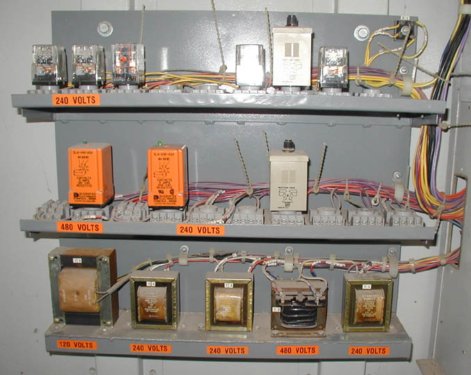
A set of narrow shelves is attached to a piece of 1/16" sheet, which is
bolted to the Unistrut in the electrical locker, and used to support
the relays and control transformers that control the car. Wiring is
laid in at the back of the shelves, using bead ties to temporarily hold
it in place. Once all of the wiring is completed, wire ties are applied
and the bead ties removed. Note that all of the relays are socketed for
easy replacement. Carrying one spare of each kind is a good thing, in
case of failures on the road.
Photo by E. Wilde, |
The main contactors for switching the car's three phase power are attached to a piece of 1/8" plate, which is bolted to the wall in the electrical locker, close to where the power wiring enters the locker from the underfloor conduits. The 240V standby contactor is to the left, the 480V trainline contactor is in the middle and the 240V diesel contactor is to the right.
We feel that it is important, for trouble shooting purposes, to have an
electrical drawing for all car components and to neatly label all of the
field wiring according to the drawings, as it is laid in. We also like
to tape three phase conductors to show the phase rotation (A - Black,
B - Red, C - Blue and A - Yellow, B - Orange, C - Brown for a second set
of conductors), thereby making sure that nothing is ever hooked up
backwards. The components themselves are also labeled according to the
electrical drawings.
Photo by Eric Wilde, |