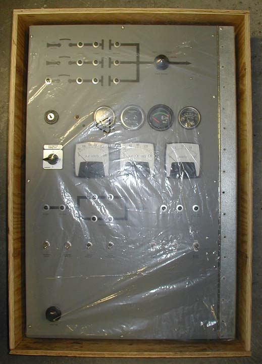
After determining the physical space constraints for the control panel,
and how it will be mounted, where the wiring will enter the box, etc.,
CAD drawings are prepared and sent for the customer's OK. In this case,
the customer specified the box dimensions and door location so that the
box would bolt right to the unistrut on the wall of the car's electrical
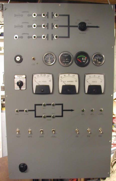
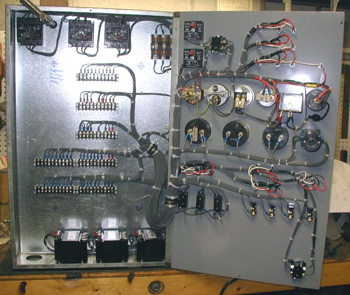
locker. From the drawings, a large, galvanized steel box is fabricated
that will house all of the control panel components. The control panel
front will be hinged, with a piano hinge, from the tab on the right (or
left, if you prefer) of the box, for easy access to all of the
components.
Photo by E. Wilde, |
The customer specified a carbon steel panel that was laid out, punched
for all of the components, painted and striped. In this view, lettering
is about to be applied, prior to overspaying the entire panel with clear
laquer for protection. A number of different treatments can be used for
the control panel marking.
Photo by Eric Wilde, |
Here, all of the control panel components are mounted on the panel. The
customer supplied some of the components used for generator set controls
(an existing control panel was disassembled and reused) and the rest
were purchased after consulting with the customer as to their
preferences. Pilot lights are long-life diode lamps and switches are
industrial type controls or heavy-duty toggles.
Photo by Eric Wilde, |
Wiring of the control panel is in progress. All of the panel wiring was
done with #18 or #14 Exane wire, supplied by the customer. The lamp test
function was implemented by diodes incorporated into the panel wiring.
Photo by Eric Wilde, |
The control panel wiring is shown nearing completion. A large bundle of
wire is being formed to the left of the panel, where it will be looped
down and back up to an attachment point on the box. This will allow
the door to easily hinge open.
Photo by Eric Wilde, |
The completed panel is attached to the box and wiring of the terminal
strips on the back of the box has begun. Field wiring will enter
through the large hole in the bottom right corner of the box and attach
to the control panel terminal blocks.
Photo by E. Wilde, |
All of the control panel wiring is completed. Three control transformers,
to provide power to the panel (Standby, HEP, Gen) and three phase failure
relays, in addition to a fuse block for the generator controls, can be
seen bolted to the box. The proposed unistrut mounting holes are marked
where the customer will field drill them.
Photo by E. Wilde, |
The completed control panel is assembled and ready for delivery.
Power monitoring and selection for the three sources of power (Standby,
HEP, Gen) are at the top. Generator controls are in the middle. Below
them are HVAC monitoring lamps and a row of toggle switches for car
lighting. The lamp test button is at the bottom. Controls for any and
all car functions can be included in your control panel.
Photo by Eric Wilde, |
The completed panel, crated and ready for shipping. The customer will
install the panel in their car and complete the field wiring.
Photo by Eric Wilde, |